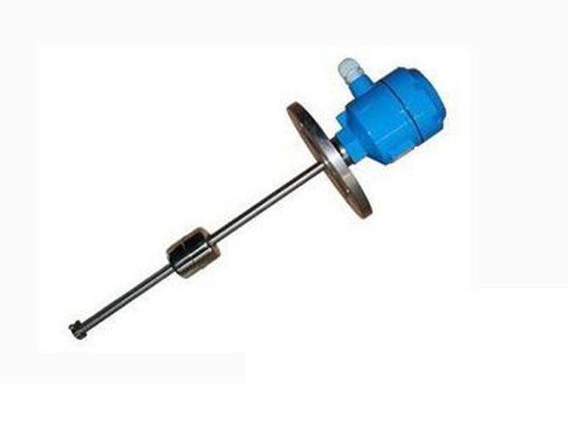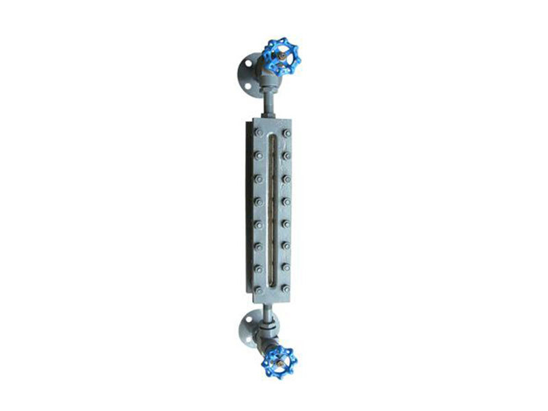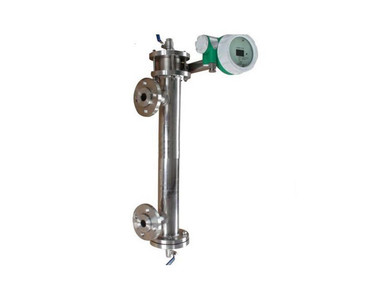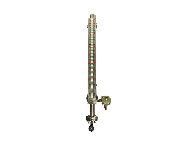
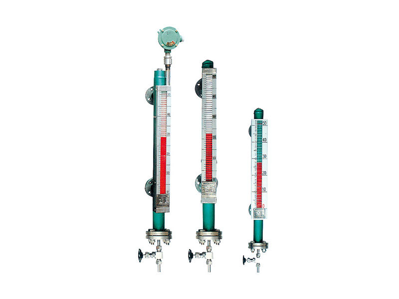
UHCZ-66 Magnetic Column Level Gauge (and Transmitter)
Zhongyou Leyi focuses on the development of complete processes and the design, manufacture and installation of complete equipment in the fields of natural gas, coalbed methane, shale gas and biogas.
Key words:
Instrumentation
Classification:
Product Description
- Product description
-
- Commodity name: UHCZ-66 Magnetic Column Level Gauge (and Transmitter)
uses and features
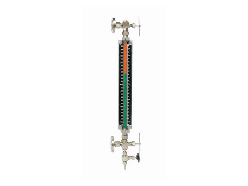
UHCZ-66 flap magnetic float level gauge is based on magnetic float as the measuring element, through the magnetic coupling of the magnetic steel to the magnetic level change linear transmission to the magnetic column display panel, intuitive and clear indication of the liquid level position, the liquid level gauge is suitable for various types of storage tanks, spherical tanks and other types of pressure or open container in the liquid level of various media, Interface measurement, the level gauge has explosion-proof function, can be used in corrosive, toxic, flammable, explosive and other dangerous places.
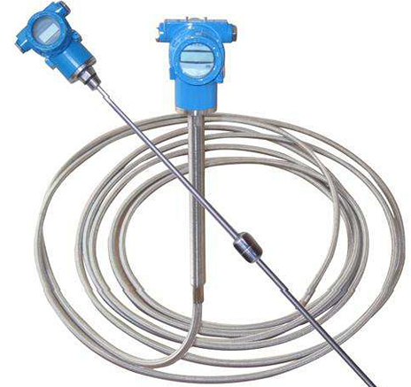
In order to expand its scope of use, liquid level switches and liquid level remote transmitters can also be added according to relevant standards and requirements to output a variety of electrical signals, among which switching signals and 4~20mA current signals are more commonly used, which can be superimposed with HART communication protocol or RS485 bus communication; The switching signal output by the liquid level switch can be used to alarm or control the liquid level; The liquid level remote transmitter converts the change of liquid level into a standard current signal of 4~20mA and uploads it to the control room to realize the remote monitoring and control of the > position of the liquid
UHCZ-66 replica magnetic float level gauge has ordinary type, steam jacket type, electric heat tracing, reed switch remote transmission, magnetostrictive remote transmission, top mounted type, Uchimura PTFE and other types of liquid level gauges, users can choose according to their needs
model preparation instructions
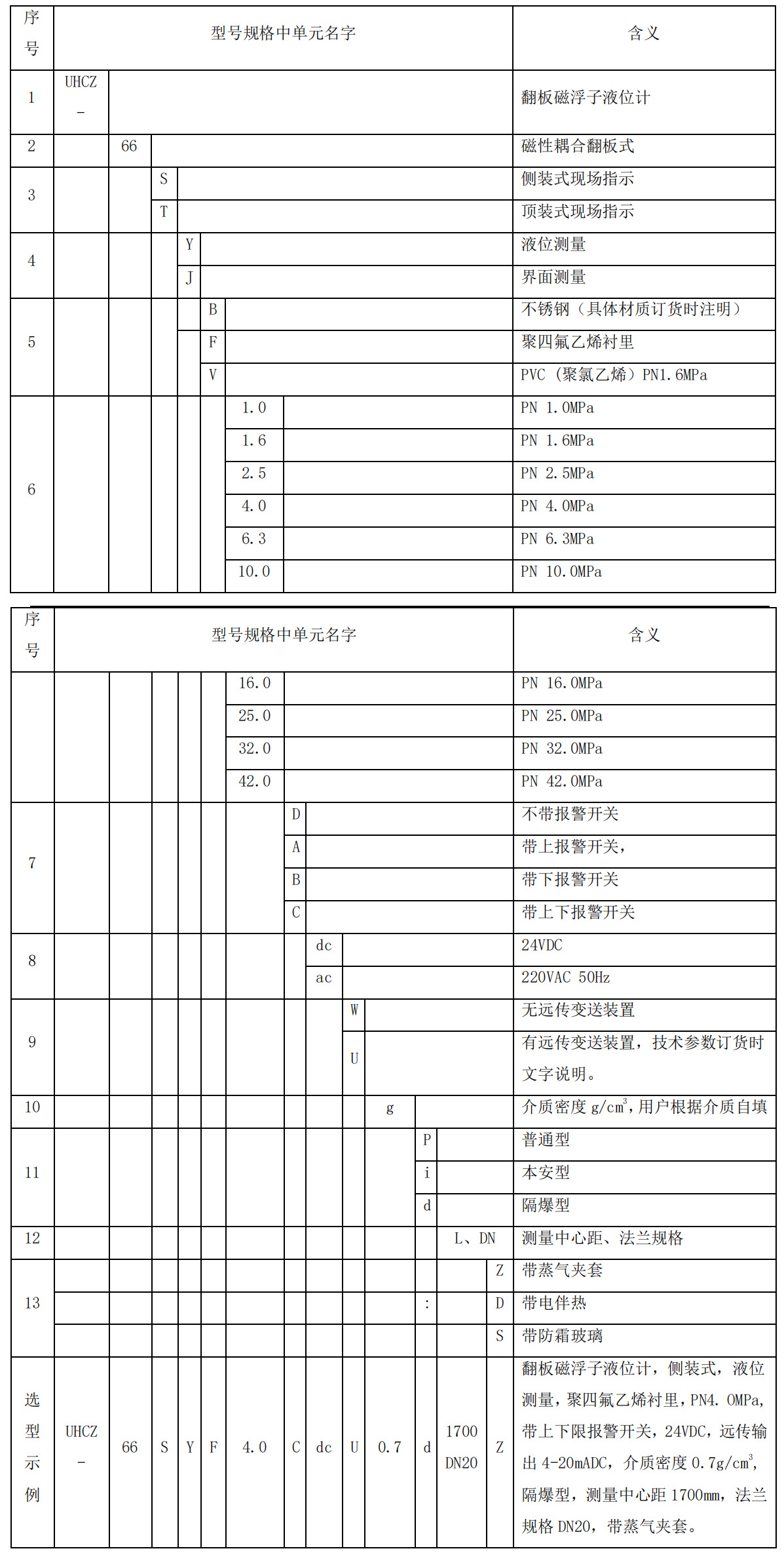
Note: M20x1.5(F) is recommended for the electrical interface of liquid level switch and liquid level remote transmitter, G3/4"(F) is recommended for the electrical interface of electric heat tracing, and ZG1/2"(F) is recommended for the connection pipe interface of vapor jacket.
structure and working principle
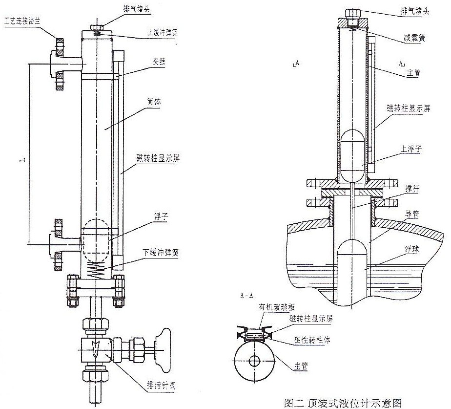
structure diagramThis product is mainly composed of the main cylinder, the upper and lower process connection flanges, the magnetic float, the magnetic rotating column display panel, the buffer spring, the exhaust plug, the blowdown valve, the liquid level switch, the liquid level remote transmitter, etc.
works
Basic working principle < br/> Flap magnetic float level gauge is based on the principle of magnetic coupling, Archimedes' law of buoyancy, communicator and other principles cleverly developed and developed for liquid level, The interface measurement device, the liquid level gauge main cylinder is installed on the container through the upper and lower connection flanges, and forms a communicator with the container, so that the liquid level of the liquid level gauge main cylinder is the same height as the liquid level in the container, so the magnetic float in the main cylinder will float up and down with the liquid level in the container; at this time, we can not see the liquid level, so we install a magnetic flap display panel on the outer wall of the liquid level gauge main cylinder, and we install 360° at the junction of the magnetic float sinking into the liquid and the floating part when manufacturing the magnetic float Annular permanent magnet magnet, when the magnetic float rises and falls with the liquid level, its magnetism is transmitted to the magnetic flap display panel through the main cylinder, and the magnetic flap is pushed to flip 180°, because the magnetic flap has two sides, red and white, so after flipping 180°, it will change to red (red below the liquid level, white above), and the junction of the two colors of the magnetic flap is the height of the liquid level (or interface).level switch works
The sensing element of the level switch is composed of a plurality of reed switches, installed on the outer wall of the main cylinder of the level gauge, when the magnetic float of the level gauge floats up and down to the set position of the level switch, due to the magnetic coupling effect to promote the reed switch to open and close according to the design requirements, the liquid level switch signal is transmitted to the control device in the instrument room, and the liquid level alarm and control are realized, and the core components are imported components to ensure a long service life and stability.
Working principle of liquid level remote transmitter:
The liquid level remote transmitter is composed of a detection rod (sensing part), a circuit unit, and an explosion-proof junction box. When the magnetic float floats up and down, the reed tube is closed due to the effect of magnetic coupling, and the change of liquid level is converted into a standard current signal output of 4-20mA, so that it can participate in the remote transmission, measurement, recording and control corresponding to the change of liquid level, with a measurement accuracy of ± 10mm, and the working life of the reed switch ≥ 100,000 times.
When the magnetic float in the main barrel of the level gauge floats up and down with the change of liquid level, because the magnetic float is equipped with a group of permanent magnets in the magnetic float, the magnetic float generates a magnetic field at the same time, and when the current magnetic field meets the magnetic field of the float, it < br / > A "twisted" pulse, or "return" pulse, is generated to convert the time difference between the "return" pulse and the current pulse into a pulse signal to calculate the actual position of the float and measure the liquid level, and converts the change in liquid level into a standard current signal output of 4-20mA to participate in the remote transmission, measurement, recording and control corresponding to the liquid level change.
Main technical performance parameters < br / > Basic performance parameters:
Measuring range: 300~6000mm can be selected arbitrarily, (special length is manufactured according to user requirements)
Indication accuracy of local display panel: ±10mm,
Medium density: ≥0.35g/cm3
Medium density difference: ≥0.06g/cm3
Medium temperature: -196°C~+550°C
Viscosity of medium: ≥10-4m2/s
Medium pressure: ≤42.0MPa
Following speed: ≤0.1m/s
Wetted material: stainless steel, PVC, PTFE, TA2, etc.,
Connection: flange, thread (according to the user's needs);
blowdown valve: M20×1.5 Male needle globe or ball valve.
The connecting flange is shown in the following table:
Note: Users can choose the flange standard according to actual needs, please indicate when ordering.
main performance of the > reed transponder transmitter is as follows:
Supply voltage: 12~32VDC, typical 24VDC
Output signal: Output 4~20mA /HART/RS485 two-wire/three-wire.
Measurement accuracy: ±10mm
Ex marking: Exdb II. BT4/Exdb II. CT6 Gb
Degree of protection: IP65/IP67
Electrical Interface: M20×1.5/NPT1/2"(F).main performance of magnetostrictive telecommunication transmitter:
Supply voltage: 12~32VDC, typical 24VDC
Output signal: Output 4~20mA /HART/RS485 two-wire/three-wire.
Measurement accuracy: ≤±1mm/±0.1%. FS
Ex marking: Exdb II. BT4/Exdb II. CT6 Gb
Degree of protection: IP65/IP67
Electrical Interface: M20×1.5/NPT1/2"(F).main performance of the level alarm switch:
Operating voltage: 24VDC or 220VAC
Output signal: NO, NC, SPDT
Measurement accuracy: ≤±5mm
Ex marking: Exdb II. BT4/Exdb II. CT6 Gb
Degree of protection: IP65/IP67
Electrical Interface: M20×1.5/NPT1/2"(F)., storage, installation of > level gauges
The transport < of the level gauge is br / > The flap magnetic float level gauge should be packed and transported, and the upper and lower connecting flanges should be equipped with protective covers, and fixed in the box, < br/> Avoid violent vibration during transportation, handle with care when loading and unloading the car, and prohibit heavy falling, so as to avoid causing the connecting flange to seal
Damage to the surface, panel glass, etc.
The storage < br/> of the level gauge The flap magnetic float level gauge should be stored in a dry and ventilated room without strong magnetic field, stacked in an orderly manner to prevent lodging, and stored
During the period, the upper and lower connecting flanges of the level gauge should be equipped with protective covers, and it is strictly forbidden to enter the particles in the main cylinder of the level gauge, and the particles < br/> Debris can have a detrimental effect on the performance of the level gauge and even cause the magnetic float to get stuck.level gauge installation
(1) Before installation, carefully check whether the model and specifications of the level gauge are consistent with the design and use requirements, and check whether each part is non-destructive.
(2) The level gauge can be installed indoors and outdoors, < br/> (3) When the level gauge is installed, welding slag, stones, iron filings and other debris are not allowed to enter the main cylinder.
(4) The level gauge must be installed vertically, and its maximum non-perpendicularity is less than 3°, and it is connected to the container through flanges or pipe fittings.
(5) There should be valves between the level gauge and the upper and lower connecting pipes of the container to facilitate the maintenance and overhaul of the level gauge.
(6) When the magnetic float is loaded into the main cylinder of the level gauge, it should be loaded in the direction of the arrow indicated in the float marking.
(7) The shell of the liquid level switch and liquid level remote transmission transmitter should be reliably grounded.
(8) Before wiring, the liquid level switch and liquid level remote transmitter should confirm that the power supply has been cut off, the power supply voltage meets the requirements, and the junction box is strictly forbidden to open the cover with electricity.(9) The connecting cable between the liquid level switch, the liquid level remote transmitter and the associated equipment is a two- or four-core (SPDT liquid level switch is a three-core) shielded copper core cable according to the equipment selection, and the cable core cross-section should be 1.5mm2. The shielding layer of the cable should be grounded in a safe place, in order to ensure the explosion-proof performance, the explosion-proof armor cable should be selected, and the outer diameter of the cable should match the hole diameter of the explosion-proof electrical joint of the liquid level switch and the liquid level transmitter, which should be Φ8mm~Φ9.5mm (if the cable is used to pass through the explosion-proof hose or cable pipe laying, please customize the appropriate thread according to the requirements), if necessary, other sealing measures can be used (such as: apply silicone sealant for sealing, etc.), after the cable wiring is completed, please tighten the explosion-proof electrical joint hold-down nut, please tighten the junction box cover to prevent water ingress, pay attention to protect the explosion-proof thread and sealing O-ring.
(10) The installation location should ensure that there is enough space for observation, maintenance, inspection and operation.
(11) Do not damage the sealing parts and seals during installation.level gauge operating procedure
(1) This instruction should be carefully read and understood before operation.
(2) Before the installation of the level gauge or after the installation of the pressure test, it is strictly forbidden to install the magnetic float into the main cylinder of the level gauge to participate in the pressure test, otherwise the magnetic float will be damaged.
(3) When the liquid level gauge is put into operation, close the sewage valve first, then slowly open the upper connecting pipe valve, and then slowly open the lower connecting pipe valve, so that the medium slowly flows into the main cylinder, so as to prevent the indicator from being unable to track and display the liquid level rising too fast, and prevent the magnetic float from being damaged by the sudden pressure rise and deformation.
(4) During the use of the liquid level gauge, if the magnetic flap rotates abnormally, the magnetic flap can be corrected by guiding the magnet to move up and down at the ruler of the display panel.
(5) When the level gauge stops running, close the lower tube valve first, then close the upper tube valve, and then open the blowdown valve, so as to completely drain the residual liquid of the medium in the main cylinder of the level gauge to prevent the medium from freezing and damaging the level gauge.
Ordering instructions (please provide the following technical parameters when ordering)
(1) Product name: model
(2) Measuring range
(3) Upper and lower connection flange diameter DN (NPS), pressure level MPa (Class), flange standard
(4) The type, density and temperature of the working medium
(5) Working environment and ambient temperature
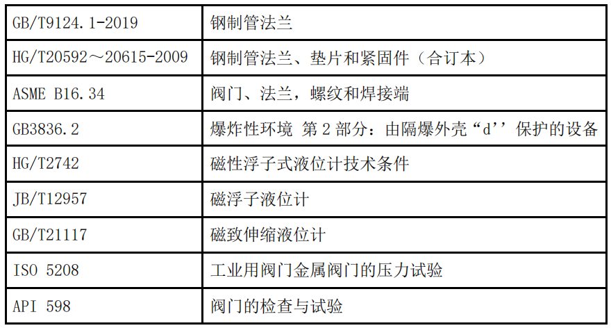
(6) Other requirements (such as: installation space, heat tracing and insulation, electrical interface, output signal and other requirements) manufacturing common standards and specificationscommon standards and specifications for manufacturing
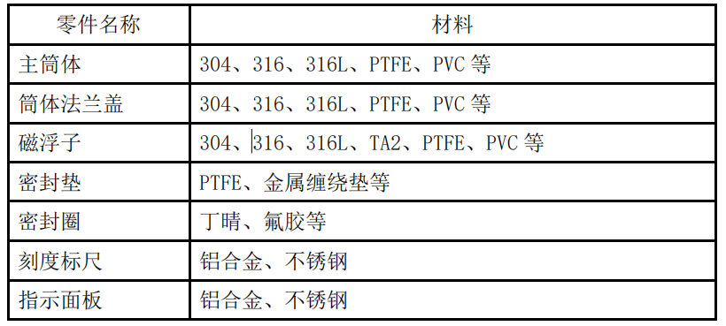
the main component material
The product is constantly improved and the configuration parameters are constantly updated. We reserve the right to change the design and parameters without informing the user; the configuration and appearance of the product are subject to the actual product.
Product inquiry
Related Products
Products
Valves
Instrumentation
Gas and skid-mounted
-
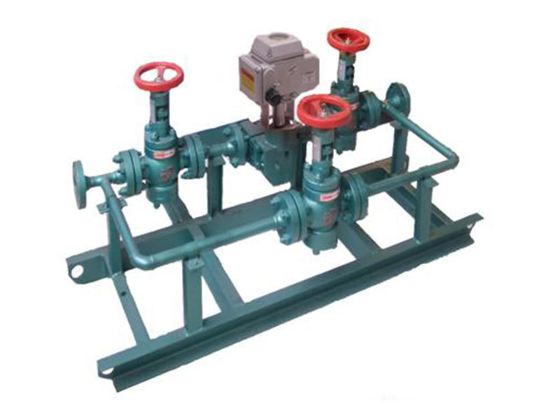
Automatic discharge monitoring system
-
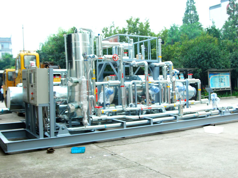
Light hydrocarbon stabilizer skid
-
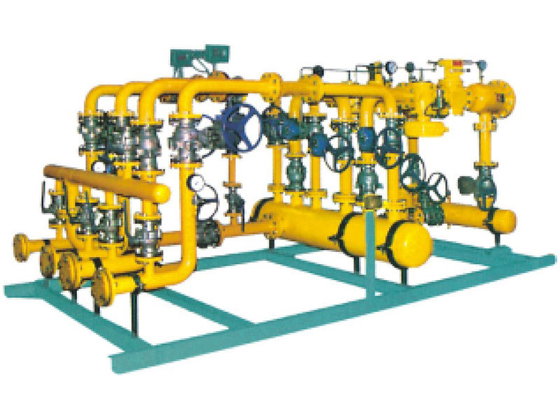
Self-consumable gas pressure regulating device of well station
-
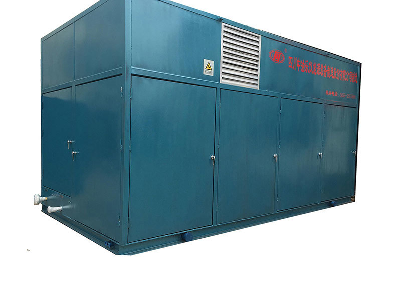
Natural gas recovery and processing unit skid
-
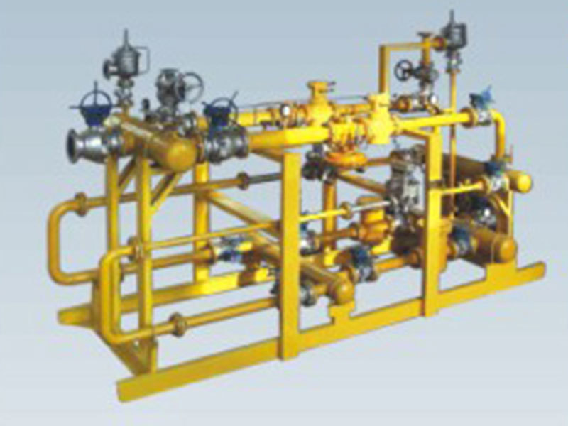
ST Series Skid-mounted Regulators
-
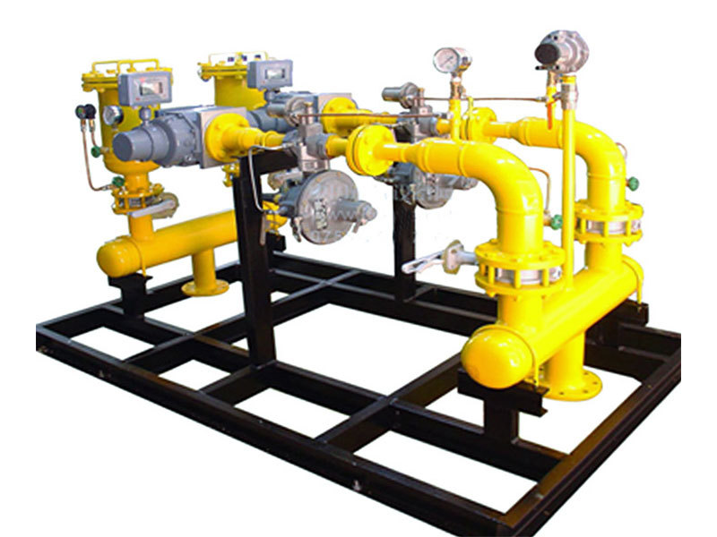
LST series metering and voltage regulating cabinet
-
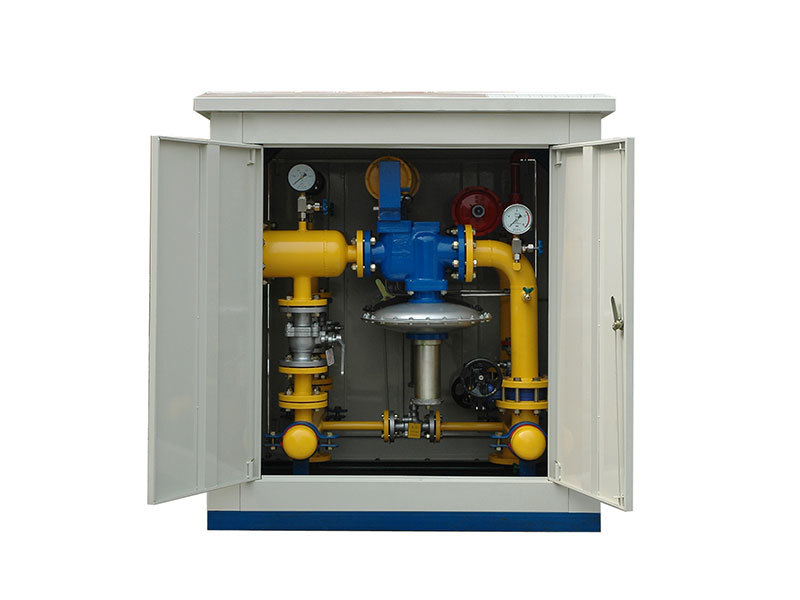
LST series standard voltage regulator cabinet
-
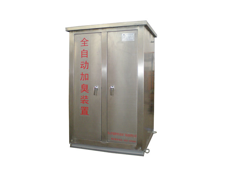
GRZJ※※Odorization (alcohol injection) device
-
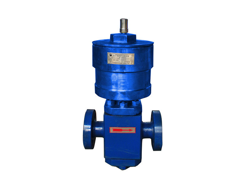
(K) TTZ-32G Regulator (with Commander)
-
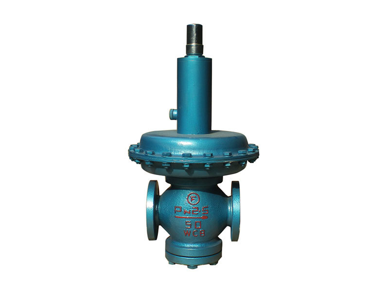
(K) TTZ-31N Regulator (Direct Action)
-
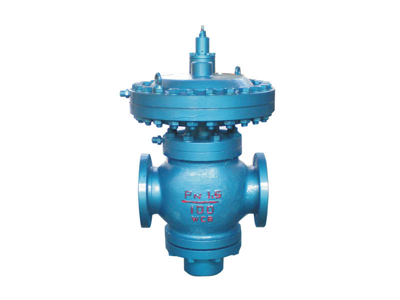
(K) TTZ1.6-6.3D type regulator (with commander)
-
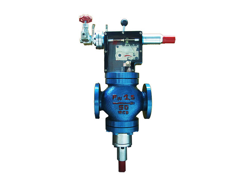
TTZ-E(Q) series fully balanced (with cut-off) new type pressure regulator
-
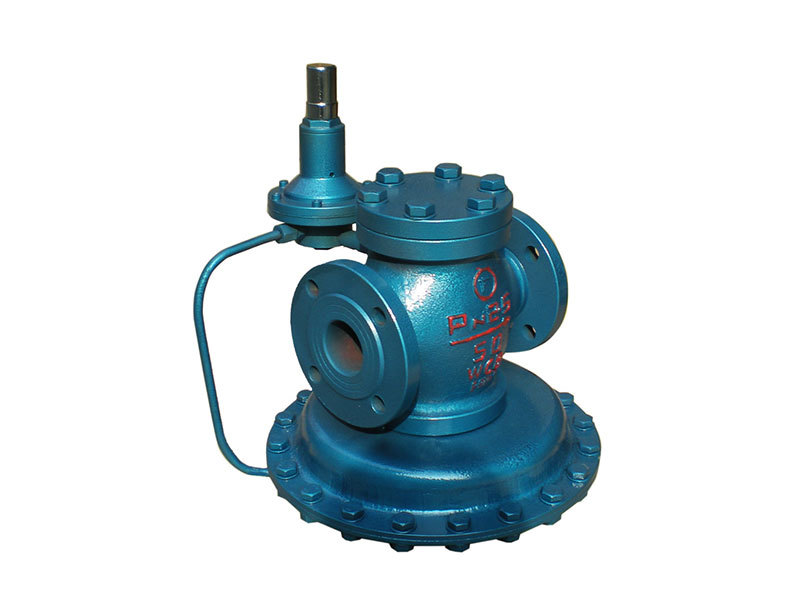
(K) TTZ-54J Regulator (with Commander)
-
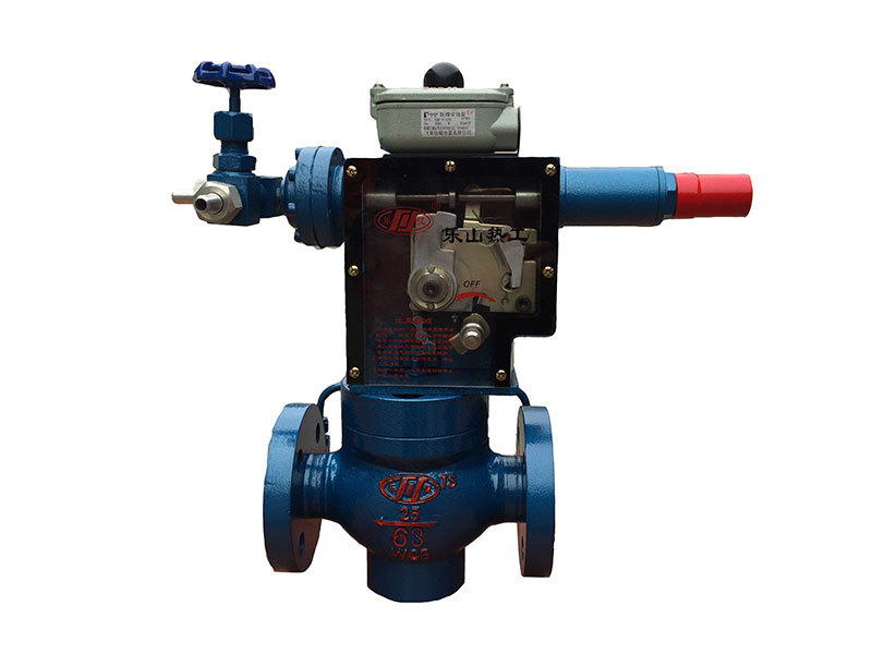
AQZ safety shut-off valve
-
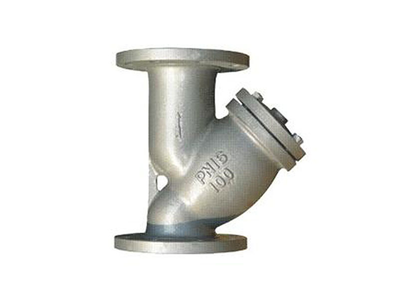
Y-type basket filter
-
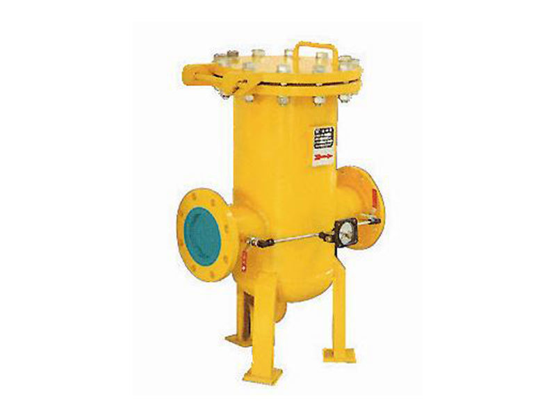
GK(J), GF type high-efficiency filter
-
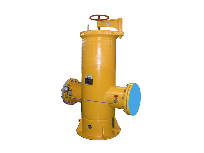
FK series gas filter
Safety bleed valve series
Globe valve series
Ball valve series
Special valve series
Check valve series
Level gauge series
Honors
Qualifications
Corporate honors
Patent certificate
-
Valve sleeve blowdown valve
-
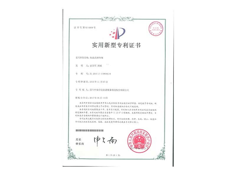
Axial flow control valve - utility model
-
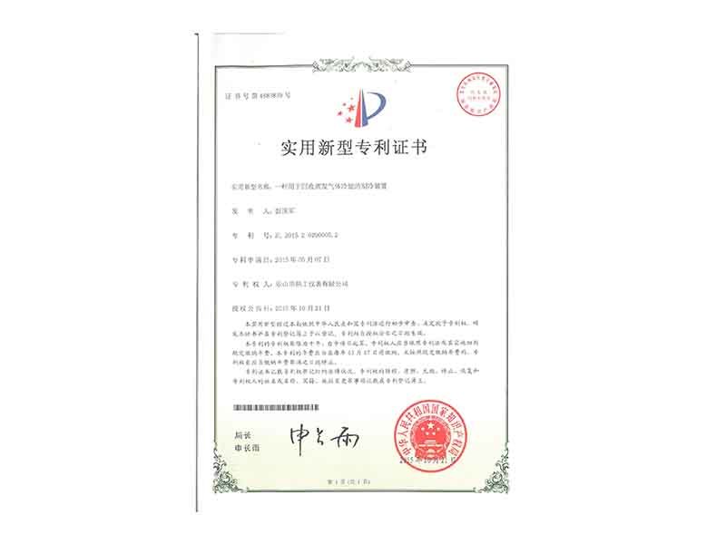
Refrigeration units for the recovery of cold energy from evaporative gases
-
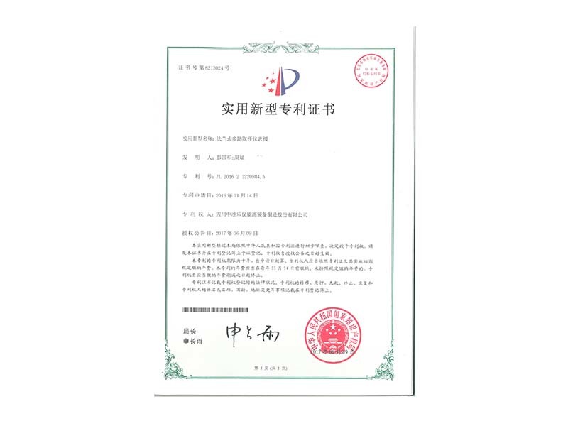
Flanged multi-way sampling instrumentation valve
-
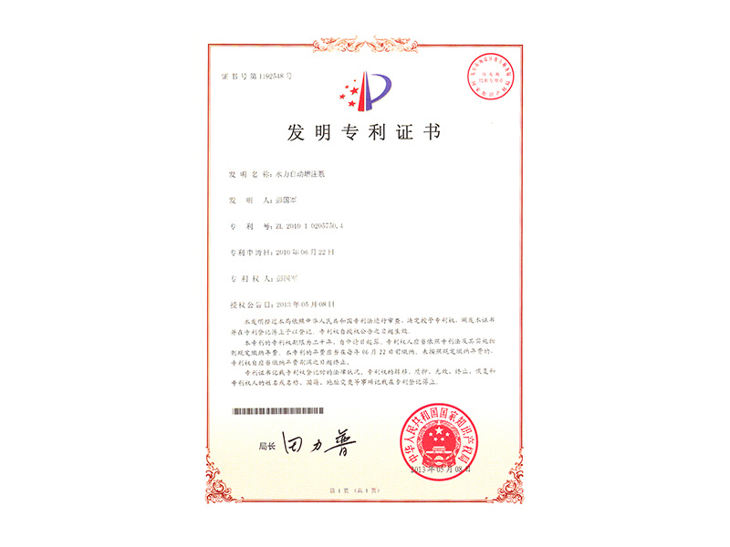
Invention patent certificate of hydraulic automatic injection pump
-
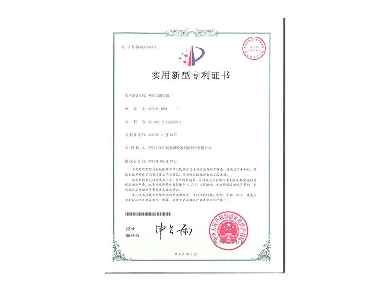
Pressure-holding regulator
-
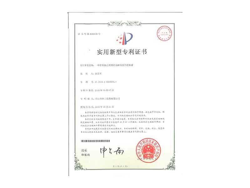
Alcohol-injected light hydrocarbon recovery unit with de-ethanizer
-
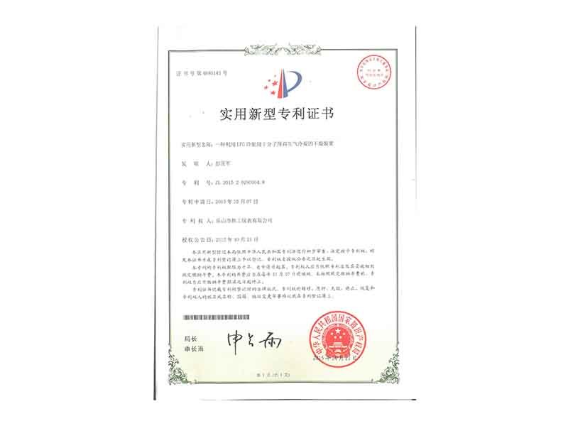
The use of LPG cold energy for molecular sieve regeneration gas condensation drying device
Successful case
Gate station project performance
Natural gas liquefaction project
-
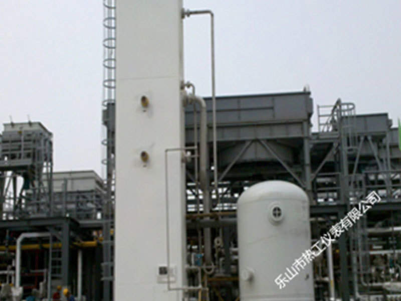
Panjin 100,000 cubic meters of natural gas liquefaction pretreatment equipment
-

Guanghui 1.5 million cubic meters of natural gas liquefaction metering and filtration equipment
-
Hesheng Petrochemical 10,000 cubic meters natural gas purification unit
-
Hefei natural gas pipeline project
-
Dehydration equipment for 200,000 cubic meters of natural gas liquefaction project in Xingxian County
Enterprise strength
Enterprise style
Copyright©2024 Sichuan Zhongyou Leyi Energy Equipment Manufacturing Co., Ltd.
Website construction:China Enterprise Power Chengdu two points

Pay Attention to Leyi

Enterprise Customer Service
SAF Coolest v1.3.1.2 设置面板 RUISD-ZDHA-OASFE-ZQQ
无数据提示
Achievement of core technology, cohesion value recognition, tailor-made product solutions for customers
You can view other columns or returnHome Page


